C-Tech Process
1.1 C-Tech Process:
C-Tech is a Cyclic Activated Sludge process. It provides highest treatment efficiency possible in a single – step biological process. The C-Tech System is operated in a batch reactor mode this eliminates all the inefficiencies of the continuous process. A batch reactor is a perfect reactor, which ensures 100% treatment. Six modules shall be provided to ensure continuous treatment. The complete process takes place in a single reactor, within which all biological treatment steps take place sequentially.
No additional Settling Unit, Secondary Clarifier is required. The complete biological treatment is divided into Cycles with each Cycle is of 2-4 hrs duration, during which all treatment steps take place. A basic Cycle comprises of the following phases which take place independently in sequence to constitute a Cycle and then gets repeated:
- Fill / Aeration (F/A)
- Settling (S)
- Decanting (D)
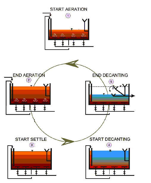
1.1.1 Fill / Aeration (F/A):
This refers to the process loading time in the cycle. Loading occurs outside of the designated settle and decant sequences during which time influent is received into the basin through an admixture (selector) reactor. Biomass from the main aeration zone is admixed with influent load in the biological selector hydrolysis reactor. Complete-mix reaction conditions prevail in the main reaction zone during this variable volume operational sequence, being typical of a fed-batch reactor operation. Aeration can be regulated to maximize co-current nitrification-de-nitrification that takes place and to insure the aerobic uptake of phosphorus previously released during anaerobic operation. The process typically employs a nominally constant rate of recycle from the main reaction zone that is pumped to a zone at the inlet end of the admixture reactor.
1.1.2 Settling (S):
The air is turned off and influent to the reactor basin is stopped. During the first five minutes of this sequence, the residual mixing energy within the reaction basin is consumed. At this time gentle bio-flocculation initially takes place, a solids-liquid interface forms under partial hindered settling conditions. Rising sludge does not occur.
1.1.3 Decanting (D):
This sequence is an extension of the settle sequence and is also totally quiescent whereby a moving weir lowering decanter is used to take the operating liquid level in the basin to its designated bottom water level reference position. In this way supernatant is withdrawn from a subsurface position under laminar flow conditions. This allows optimum removal over the decant depth without entrainment of settled solids or floating debris. Upon completion of the supernatant liquid removal sequence, the moving weir decanter returns to its rest position located out of liquid. Completion of the decant sequence terminates the designated use of the basin as a stratified, interrupted inflow reactor. Typically, fill sequencing begins while the decanter is travelling to its upper rest position.
2.0 C-Tech Components
The C-Tech System comprises the following main components:
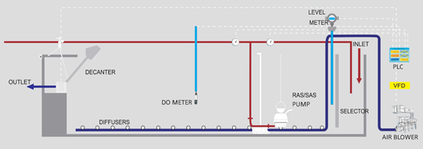
1. Selector:
Biological Selector Zone prevents sludge foaming and sludge bulking.
2. DO Meter:
DO Meter helps in measuring DO concentration available in the basin and also Oxygen Uptake Rate (OUR) based control of the process. This ensures 30 – 40% power saving.
3. Decanter:
The clean supernatant is removed from the Basin using a Decanter Assembly, complete in Stainless Steel construction. During Decanting, there is no inflow to the Basin. The moving weir type Decanter travels slowly from its “Park” position to a designated Bottom Water Level with the help of a geared Drive. Variable Frequency Drive (VFD) is provided to control the rate of movement of Decanter. After the required level of supernatant is removed, the Decanter is returned to its “Park” position through reversal of the geared Drive. The Basin is now ready for the next Cycle to begin. The C-Tech decanter is specifically designed to be positively free of entrained settled and surface (floating) solids at all times.
The new generation decanter developed by SFC and tested in Munich University is having enhanced hydraulic capacity to handle higher peak loads at all decanting depths.
4. Diffusers:
Fine bubble polyurethane membrane diffusers are provided for efficient transfer of oxygen from air to meet the process demand. Air grid with adjustable supports are provided for installing all diffusers at same level and hence ensuring uniform air distribution across plan area.
5. Air Blowers:
Air Blowers supply required air as per process demand. Air blowers are controlled through PLC as per OUR based control logic. Variable Frequency Drive (VFD) is provided to blower to ensure proper control of air supply there by optimizing the power consumption and reducing power bill.
6. Submersible Pumps for Sludge Recycle (RAS) and Sludge Wasting (SAS):
RAS pump recirculates part of biomass into selector compartment during fill/aerate mode whereas SAS pump pumps out excess sludge from C-Tech basins during decanting period for further disposal.
7. PLC:
For complete automatic cycle control and operation. This reduces cost of Manpower as complete operation can be hooked to a central Control Desk.
© Copyright 2018 by SFC Environmental Technologies Pvt. Ltd. All Rights Reserved | Designed & Developed by Crest IT Consulting